Copper has superior cooling capacity than aluminum and is the preferred heat sink material for telecommunications and high power electronics. However, the weight and cost or copper limits the size of the heat sink packages. Therefore for larger electronic enclosures a hybrid design, using copper for a localized heat sink joined to an aluminum frame with good thermal contact can significantly improve the cooling performance of a heat sink package.
Joining copper to aluminum poses it challenges. Cu and Al cannot be welded easily due to the intermetallics that form when Cu alloys with Al in the weld pool. Alternatively, brazing cannot be done since melt point of aluminum is below the typical Cu-Ag braze filler metals (silver solders) used to braze copper. These issues leave “soldering” as the metal filler joining process of choice. But alone, soldering of Cu to Al has challenges. Solders, typically Sn-Ag based, cannot easily wet and adhere to aluminum without first plating the aluminum with nickel or using very aggressive chemical fluxes which themselves are incompatible with soldering to copper.
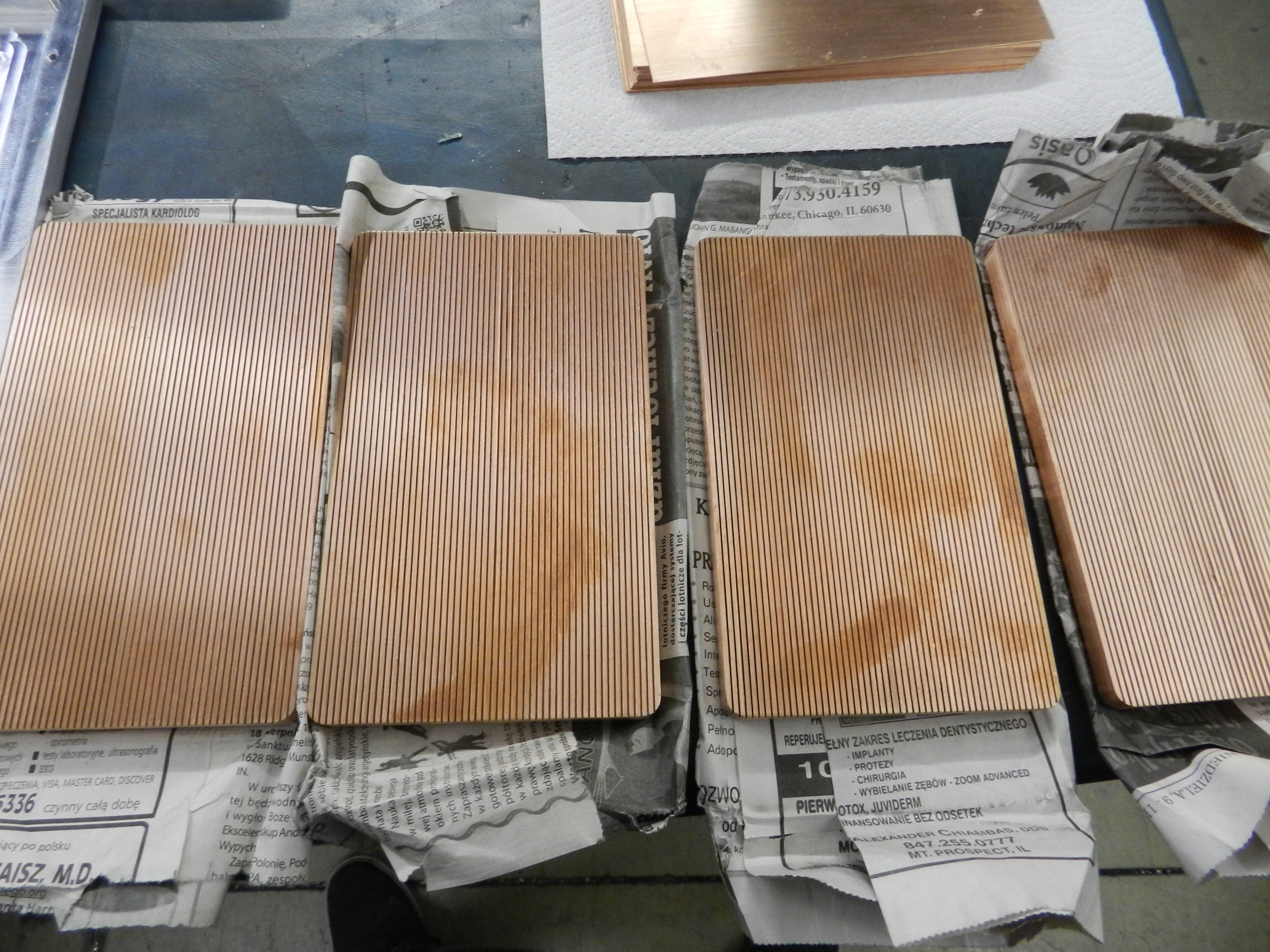
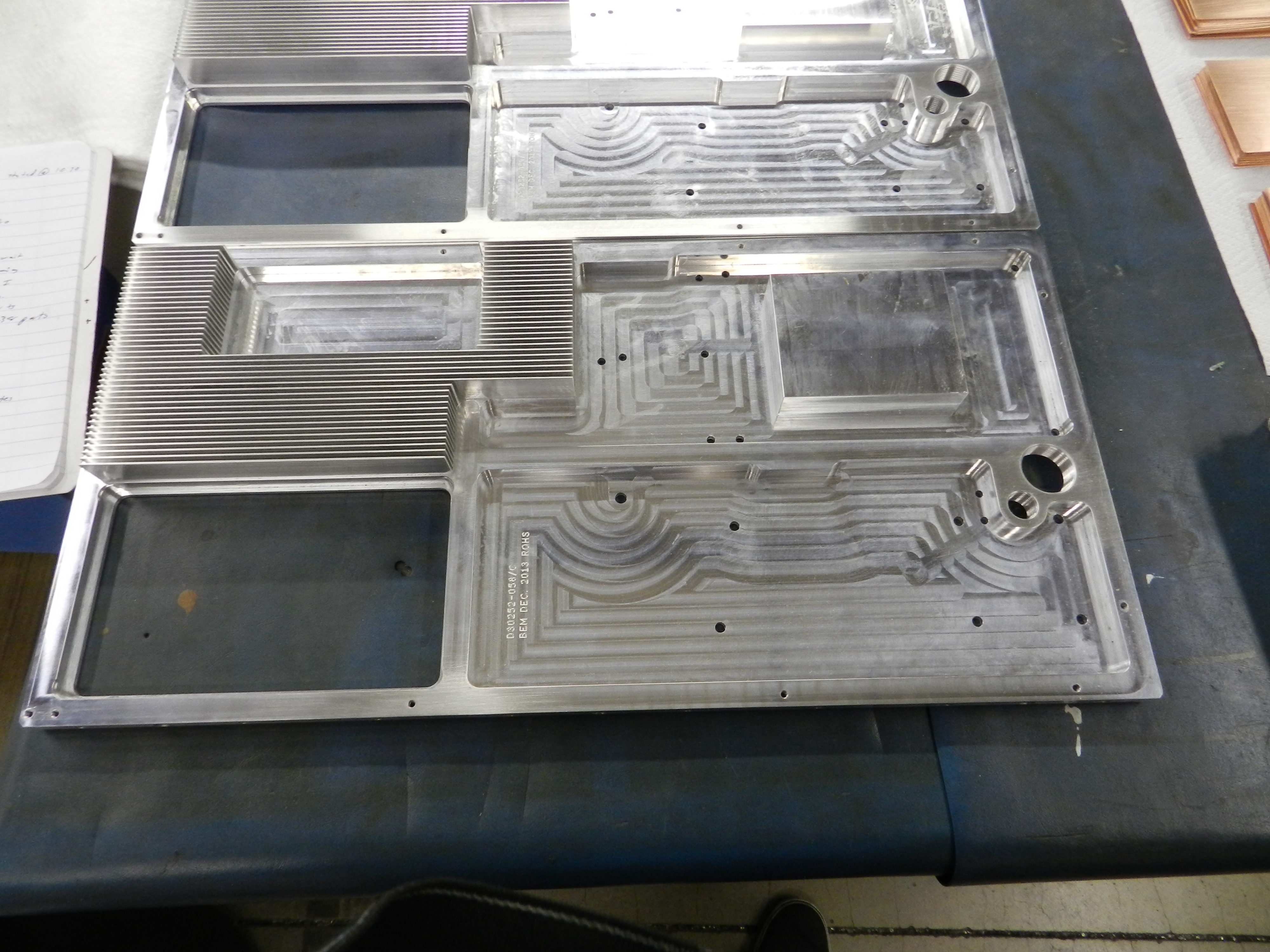
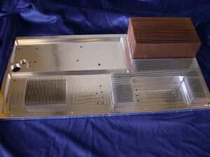
S-Bond Technologies, working with its customers has demonstrated its active solder, S-Bond 220-50, join Cu to Al in all configurations. The figures below show an example of where a copper- finned heat sink assembly was S-Bond joined into a finned aluminum package. In this assembly, the Cu-fins were individually S-Bond soldered into copper heat sink base, after which the Cu fin-base assembly was then S-Bond joined into the aluminum base at 250C. This soldering temperature well below the softening temperatures for the aluminum frame and low enough that the thermal expansion mismatch between Cu and Al did not distort the bonded assembly when cooling.
Hybrid heat sinks, combing the thermal benefits of copper with lightweight aluminum are taking advantage of the capabilities of active solder joining. For tough dissimilar materials and copper and aluminum bonding challenges, Contact us.
Graphite and carbon felts are increasingly being used for applications in solar, LED, medical, semiconductor, automotive and energy storage systems.
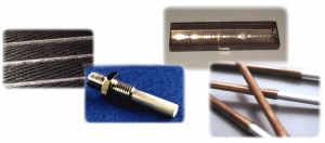
S-Bond Technologies (SBT) has customized it S-Bond (S-B) processes to bond graphite felts to metals for such applications. In the process, graphite felts are first S-B metallized using a paste and vacuum process to create a metallurgical bond between graphite and the SBT active solder filler metals. After S-B metalizing of the graphite, only the tips of the felt surfaces are metallized and thus solderable to the opposing metal plates that are coated with SBT active solders. The S-B metallization process does not fill the open cells of the graphite felts with S-B alloys, hence its advantage for bonding open cell structures. (more…)
Metal to metal bonding is used in many applications for fabricating components where the metallic parts are too large or too complex to make from one piece of metal or the assembly contains dissimilar metals for various functions, such as: 1) physical properties such as electrical or thermal conductivity, 2) differences in thermal coefficient of expansion, 3) differences in corrosion, 4) differences in strength and/or modulus. For designers to utilize the optimum combination of metal properties, it is useful to have metal to metal bonding properties that optimally combine metals in an assembly.
Bonding technologies include: 1)Mechanical fastening, 2) Epoxy bond, 3) other Metal Adhesives, 4) Diffusion Bonding, 5) Explosive Bonding, 6) Weld & Weld Cladding, 7) Ultrasonic Welding, 8) Brazing and Soldering and 9) specialized active solder bonding. For strength mechanical fastening and welding are favored… for low cost, epoxy and other adhesive metal bonding are best but have limitations with regard to sealing, thermal conductivity, and stability over time. Diffusion and explosive bonding perhaps provides the best strength and interfaces between metals. However; for the best combination of bond properties and the least effect on base metal properties; ultrasonic welding, brazing, or soldering are the processes of choice. The choice of bonding process also entails the area of bond required, the joints’ physical properties and the effect the bonding process has on the base metal properties… all these are considerations when selecting bonding process. (more…)
S-Bond material joining applications enable engineers to use multiple materials, such as materials and ceramics, in a variety of applications. However, just because aluminum and steel can be joined, as one example, does not mean that the joining process cannot introduce deformations or other issues.
Thermal Expansion Concerns in Bonding
When soldering two different types of metal together, both surfaces have to be heated in order for the solder to bond to both components. Materials expand as they heat, and different metals do so at a different rate. This can create problems as the joining site cools back down.
Two examples of materials that react easily to heat are aluminum and magnesium, which can expand at twice the rate of carbon steel and iron. If an aluminum sheet is soldered to a sheet of carbon steel, during the cool-down period the combined piece will warp with a slight curve. With more brittle components such as those made with ceramics, the combined part can shatter based on expansion during bonding and later cooling.
Solutions for Dissimilar Coefficients of Thermal Expansion
S-Bond® active solders are being used extensively as a high conductivity bonding solution for foam cored phase change materials foam cored heat sinks. Increasingly, thermal management in electronics is the limiting factor in performance and/or life of electronics as higher power and higher speed in electronic devices generate more intense heat. High brightness LED’s, high speed/high bandwidth telecommunications, avionics, satellites and solid state conversion devices all have transient and steady power states where intense heat is generated and needs to be channeled away from the electronic device to prevent performance loss or permanent damage. The electronic industry is relying on a host of devices from conventional heat sinks with fins and fans to heat pipes and vapor chambers to more exotic materials and composites that include pyrolytic graphite or diamond. S-Bond materials and processes have been proven to be a good solution when bonding these various components and materials with a metallic “thermal interface material (TIM)” rather than filled polymeric bonding agents.
When electronics have a high transient heat output thermal engineers are using “phase change” heat sinks. Such heat sinks utilize “phase change materials (PCM’s)” that when exposed to heat absorb it very quickly and effectively as the material “changes phase”… either going from solid to liquid or liquid to vapor. Materials with high latent heats of fusion or latent heat of vaporization at or near the maximum temperatures that electronics are being used in the core of such heat sinks. In PCM heat sinks during the phase change there is the potential to rapidly absorb a high heat load… that can later be more slowly released to the atmosphere with cooling fins as the phase change is reversed and the heat is released away from the electronic device.
Two of the most used PCM’s are paraffin and water… each has a high latent heat of fusion or heat of vaporization, respectively. The challenge in the use of PCM’s is to overcome their relatively low thermal conductivities. For example, in heat sinks with paraffin as the PCM, when the heat transfers from the electronic device into the heat sink package, the outer layer of paraffin melts and then slows the transfer of heat into the solid paraffin core. To offset this heat flow limitation, designers are incorporating metallic or graphitic foams into the core of the heat sinks. The foams’ cells separate the PCM’s into small reservoirs that are surrounded by high thermal conductivity cell walls that then transfer the heat to a small PCM filled pore in the foam and therefore quickly melts the paraffin or vaporizes the water. Later in the “reverse” cycle, the conductive foam “cell walls” transfer the heat out of the PCM filled pores to solidify or condense the full volume PCM in the heat sink.
S-Bond joining has found excellent application in paraffin based PCM heat sinks in combination with graphitic foams (PocoFoam® or K-Foam®). S-Bond can effectively bond to graphite and graphite foams to heat sink package materials such as aluminum, copper and many heat sinks composites such Al-SiC, Al-Gr, Cu-W or Cu-Gr. In such graphite core/paraffin heat sinks. S-Bond Technologies has S-Bond metallized the Gr-Foam preparing for it to be soldered directly to the heat sink package. After S-Bond metallization, various S-Bond solders and processing can be used to bond the graphite foam to the components of the heat sink.
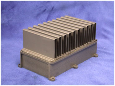
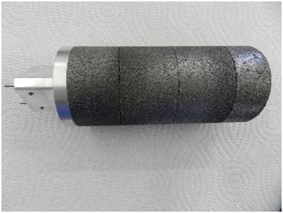
Figure 1 shows a PCM core finned Aluminum heat sink box used to cool high power laser diode packages mounted on the flat side opposite the side with the fins. The aluminum box contains a core of graphite foam bonded to the walls and base of the aluminum enclosure. The aluminum enclosure is then heated to 100˚C and filled and infiltrated with paraffin PCM’s. After filling the enclosure is sealed and the assembly is a PCM heat sink. When the laser diodes are on for intermittent periods of time the graphite foams thermally bonded to the wall of the enclosure heat the PCM… later when the heat load from the diodes are off, the bonded fins with air convection assist, cool and solidify the paraffin PCM to get the heat sink ready for the next thermal cycle. S-Bond active solder joining enabled the graphite foam to have an excellent thermal interface to the enclosure without filling the graphite foam and compromising the graphite foam’s ability to hold and transfer heat quickly to the paraffin PCM.
Figure 2. Graphite foam cored PCM heat sink for hot fluid channeled into the core.
Figure 2 shows another type of PCM cooling. The alternating bonded fluid circulating aluminum tubes bonded with S-Bond sandwiched between S-Bond metallized and bonded graphite foam plates. The stack is later encased in an enclosure and paraffin PCM is infiltrated into the foam to make a large ~ 24” x 24” x 12” PCM heat sink. When heated fluids circulate in the aluminum tubes the PCM filled graphite foam core rapidly absorbs the heat from the fluid.
Figure 3 illustrates another style of PCM heat sinks that are mounted around a central heat pipe. In this design, S-Bond metallization of the faces and ID’s of the graphite annular rings permitted a graphite foam outer core to be become an effective PCM heat sink for a heat pipe cored thermal management device.
Contact us to evaluate how S-Bond can be used to enable your thermal management components to be made and how phase change material (PCM) heat sinks can be effectively incorporated into your designs.
Figure 1. Illustration of vapor chamber heat spreader with CPU heat source
Heat pipes and vapor chambers are used to transfer and/or spread heat from concentrated heat sources such as high brightness light emitting diodes (LEDs) and high computing speed CPUs. These active thermal management devices are enclosures/tubes that have porous wick materials lining the walls that provide condensation surfaces and small connected pores that via capillary force, transfer condensed fluids that were originally vaporized at heat source surfaces. When the vapor is transported via convection to the cooler surface to condense, the fluid is then channeled back to the heat source surfaces in a continuous cycle, in effect pumping the heat out of the package without using external power surfaces. Figure 1 illustrates a vapor chamber used to cool a mounted CPU.
Figure 2. Light emitting diode package bonded to vapor chamber
Thermal management is critical in the life and performance of such electronic components that all employ a variety of thermal interface materials (TIMs). With increased power and speed, the polymer-based TIMs being used today are limiting and metal bonding with solders is growing in application. Conventional Sn-Ag soldering temperatures can overheat the thermal fluids in heat pipes and chambers while Indium (In) solders are expensive and do not bond as well as active solders. Responding to this need, engineers at S-Bond® Technologies have announced its latest alloy, S-Bond® 140 as an effective TIM for bonding CPUs or LEDS to heat pipes and vapor chambers. The Bi-Sn-Ag-Ti alloy can wet and join to all metals including aluminum and to most ceramics and glasses. S-Bond® 140 is lead free, does not require plating and flux thus keeping electronic and LED packages clean.
Figure 3. S-Bond 140 bonded heat pipe assembly
Figure 2 illustrates a high brightness LED array that has been bonded to a Ni-plated copper vapor chamber with S-Bond 140 solder. This technique provides a high strength and high thermal conductivity metallic solder bond. Figure 3 is another example showing S-Bond 140 solder bonding copper heat pipe tubes (water as the phase change fluid) into aluminum slots to enhance the cooling from the heat pipe to the aluminum package base without plating and flux.. Normally when soldering heat pipes over 200°C, the water in the heat pipe goes to vapor and the resultant pressure distends/distorts the thin copper tube walls. Lower temperature metallic solders, such as S-Bond 140.
Solder bonding is a versatile lower temperature bonding process that is used in joining a range of metals, ceramics, glass and metal: ceramic composites. By definition, solders are joining filler metals that melt below 450°C. Solder bonding is typically used in the assembly of structures for its good thermal and/or electrical contact or for creating seals. The advantage of solder bonding stems from lower temperature exposure (less that 400°C), compared to brazing when joining thermally sensitive materials. Alternatively, compared to bonding with epoxy adhesives, solder bonding is a more conductive bond, but does require higher temperature exposure and the wetting of the molten metal to the bonding surfaces.
Figure 1. S-Bond joined heat pipe assembly bonding copper pipes to aluminum base
Because of it excellent thermal and electrical conductivity, solder bonding finds application in the manufacture of sputter targets, heat spreaders and cold plates and other related thermal management components. Solder bonding is also used to seal ceramic:metal and glass windows used in optical based sensors and in other fluid cooled enclosures. Figures 1 and 2 show several typical solder bonded parts.
Solder bonding (e.g. S-Bond®), despite being versatile and capable of joining most materials, one must consider several issues when active solder bonding…
Thermal expansion mismatch
Size and shape of bonded parts
Interaction with post solder bond processing
Galvanic corrosion coupling
Figure 2. Aluminum to copper cooling tubes and ceramic to plated copper sputter targets.
In every application being evaluated for a solder bonding solution, the component and process design needs to consider the following issues.
Minimize CTE mismatch of bonded materials to prevent distortion or fracture.
Understand post bonding processes to prevent damage of bond interface.
Know Service Temperature and Thermal cycling effects on bond interface.
Understand effects of service environment on bond interface corrosion
Thermal expansion mismatch (CTE): solder bonding requires heating the component parts in an assembly to 120 – 400°C, depending on the solder filler metal being used. When similar materials are being joined there is no CTE mismatch so it is not a concern. However; many times solder bonding is being used to lower the CTE mismatch… but despite the lower bonding temperature, it is not alone a “silver bullet” universal solution. Even when heating to 250°C, melting for Sn-Ag based solders, upon cooling once the solder solidifies it can transfer a strain. Then the CTE derived stresses can distort metal assemblies, fracture a glass or ceramic components or fracture the bond. Thus, one needs to minimize CTE mismatch stresses by selecting assemble component materials that are as close as possible in CTE.
When matching CTE is not practical, then one should design the component parts with size and thickness in mind… larger bond areas will “accumulate” more stress and lead to more distortion and/or fracture. A solution for larger parts is to “tile” the component parts; by tiling (mosaic) the strain mismatch accumulation is interrupted and lower the accumulation of stress in the assembly.
Post solder bond processes such as post solder bond heating either with another solder process, welding or bake outs to dry or cure components. Coatings may also be required on a bonded assembly where the heat and or chemical exposure of the coating process, as in electro-plating (see the coating blog article), interacts negatively with the solder bond.
When post processing a solder bonded part, temperature exposures typically should be below 90% of the solidus temperature (temperatures where solder alloys begin to melt) to maintain the bond. The thermal cycle itself can be damaging to the bond, even if the temperature is below this limit, especially with assemblies that have dissimilar materials. The processes that can degrade solder bonds include, other solder steps, welding, bake out or curing, and coating. Therefore; one needs to understand their impact on the solder filler metals and the solder bond interface.
Service conditions can also limit the performance and life of solder bonds. Temperature in service generally needs to be restricted to be below 80% of the solidus temperature of the solder filler metal (although active solders such as S-Bond® can be used up to 90%) to maintain sufficient bond strength. Thermal cycles are more damaging than constant temperature exposure and can be more damaging when CTE mismatched materials. Joint design can mitigate some of these effects by…
Selecting component materials to lower CTE mismatch
Minimizing area of solder bond and consider tiling, if practical
Using thicker cross sections, if possible, to limit distortion
Orienting or mechanically supporting solder bonds/seals to lower bond stresses.
With proper design solder bonded assemblies can be superior to epoxy bonded joints and work very well and compete with brazed or welded joints
We receive many inquiries to silver solder, solder or braze components and many times there is confusion over this terminology and the various materials and processes used to bond metals, ceramic and/or glasses. This short article offers some clarification to the distinctions between soldering and brazing such that you can make informed decisions about your needs. (more…)
Active solder, S-Bond® alloys have been developed to bond to a range of metals, ceramics and composite materials without the need for fluxes of preplating. In particular, such active solder alloys have an affinity for joining aluminum to itself and other metals and ceramics. Aluminum soldering has gotten simpler with the emergence of such S-Bond® solders. Just melt the S-Bond filler metals, mechanically spread them on the surface via brushing, rubbing, or via ultrasonically activated spreaders and the alloys will wet, adhere and provide a base for bonding. In a subsequent step, when two molten pre-tinned S-Bond layers are pressed or slid together the S-Bond layers will activate a strong solder bond. (more…)
 Copper has superior cooling capacity than aluminum and is the preferred heat sink material for telecommunications and high power electronics. However, the weight and cost or copper limits the size of the heat sink packages. Therefore for larger electronic enclosures a hybrid design, using copper for a localized heat sink joined to an aluminum frame with good thermal contact can significantly improve the cooling performance of a heat sink package.