Active Solder Joining for Semiconductor Processing
S-Bond Technologies’ active solders are finding wide application in semiconductor processing equipment. Their capability to join a wide range of dissimilar materials and the fact that as a filler metal, their bonds are thermally conductive make S-Bond solders far superior to many other commercial bonding/thermal interface materials. Semiconductor processing applications include…
- Sputter Targets
- Probes & Sensors
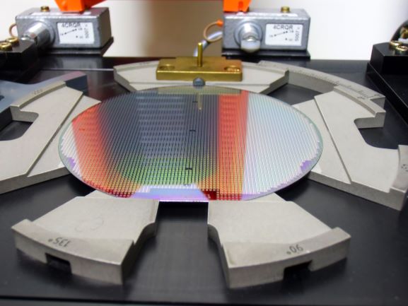
- Wafer Handling
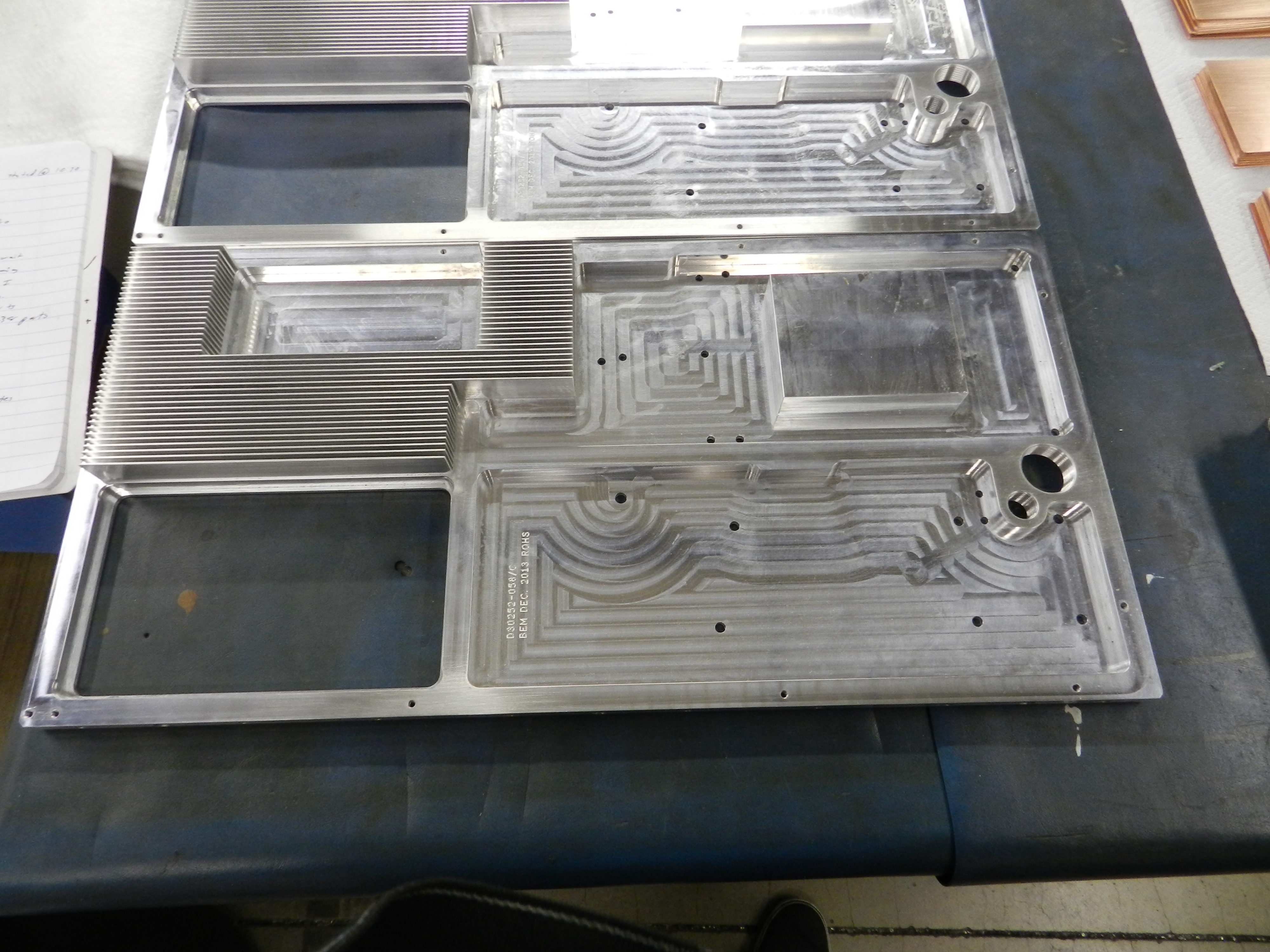
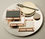 In sputter targets, the deposition/target materials is sputtered (high energy ion impacts displace a target’s atoms) onto an opposite surface to form a functional coating or other element layer in a computer chip, TV screen or other semiconductor device. The high energy impact of the deposited films require “sputter targets” to be cooled to keep the target material layer from melting. To cool the target, water is circulated in an aluminum or copper base plate. S-Bond active solders can bond all metals and most ceramics that are commercially used to produce sputtered films. Active solders can bond these sputter targets to either Copper or Aluminum, bonding them at low temperatures (which minimizes thermal expansion mismatch stresses), without flux contamination/entrapment (which will contaminate the sputtering plasma), and with excellent thermal conductivity (a metallic bond with nearly no voids).
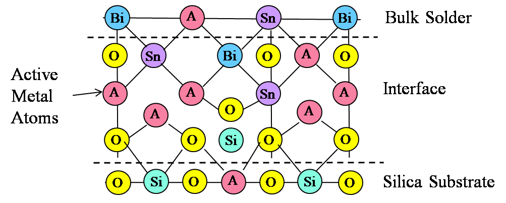
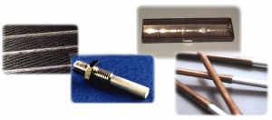
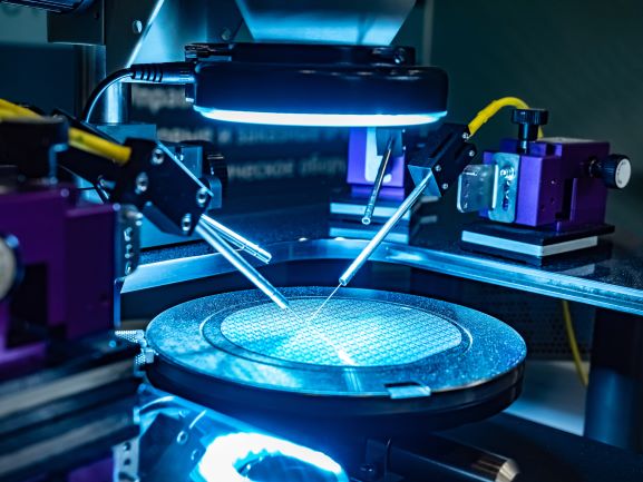 For probes and sensors, S-Bond active solders can bond silicon or carbide/carbon based devices (MEMS or other semiconductor based probes) directly to metal and metallic conductor leads. The low temperature active solders, when joining semi-conductor devices, impart low residual stresses and the joints are electrically and thermally conductive… good for signal transmittance and cooling.
Piezoceramics such as Pb-Zirconates (PZT) that impart force/small displacement or create ultrasonic pulses, can be bonded direct to metals with active solders. Bonding is accomplished bonded below their curie points with acoustically sound interfaces that can transmit sound effectively. Such piezoceramic based sensors and actuators are used in accurately measuring gas flow and can be used on gas control in MOCVD processes used to deposit and etch computer chips. S-Bond active solders can wet and adhere to most piezoceramics all without pre-plating and chemical fluxes… as such they are finding excellent application in probes and sensors used on semiconductor processing.
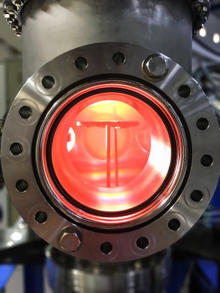
Wafers (silicon or other) are placed into energetic plasmas and other beams to deposit then etch a complicated surface morphology in layers to create semiconductor based chips. The high heat energy into the wafer needs to be removed through water cooled wafer handling devices such as the pedestals the wafer sits on in their processing chambers. If not cooled, the interdiffusion of the fabricated on the wafer. With the latest 300mm diameter wafer technology over a $1M work of chips can be on a wafer.
 The high energy levels used in semiconductor processing requires well cooled and reliable handling equipment. S-Bond active solders can intimately join copper and aluminum as well as other thermal management materials such as AlSiC and pyrolytic graphite.
If you would like to see how S-Bond active solders can improve your semiconductor processes and handling and measuring equipment, please Contact US.
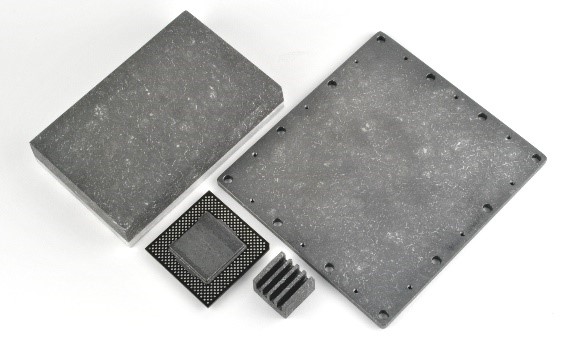
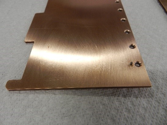
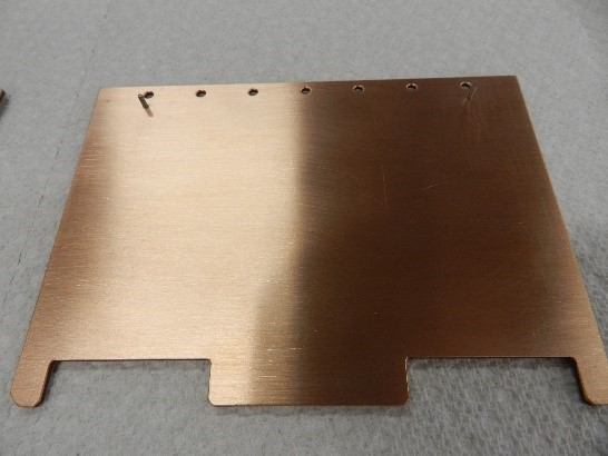
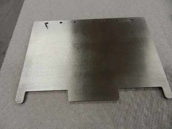 Figure 2. Copper and Aluminum clad CarbAl-G circuit boards.

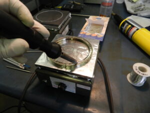
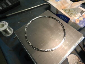
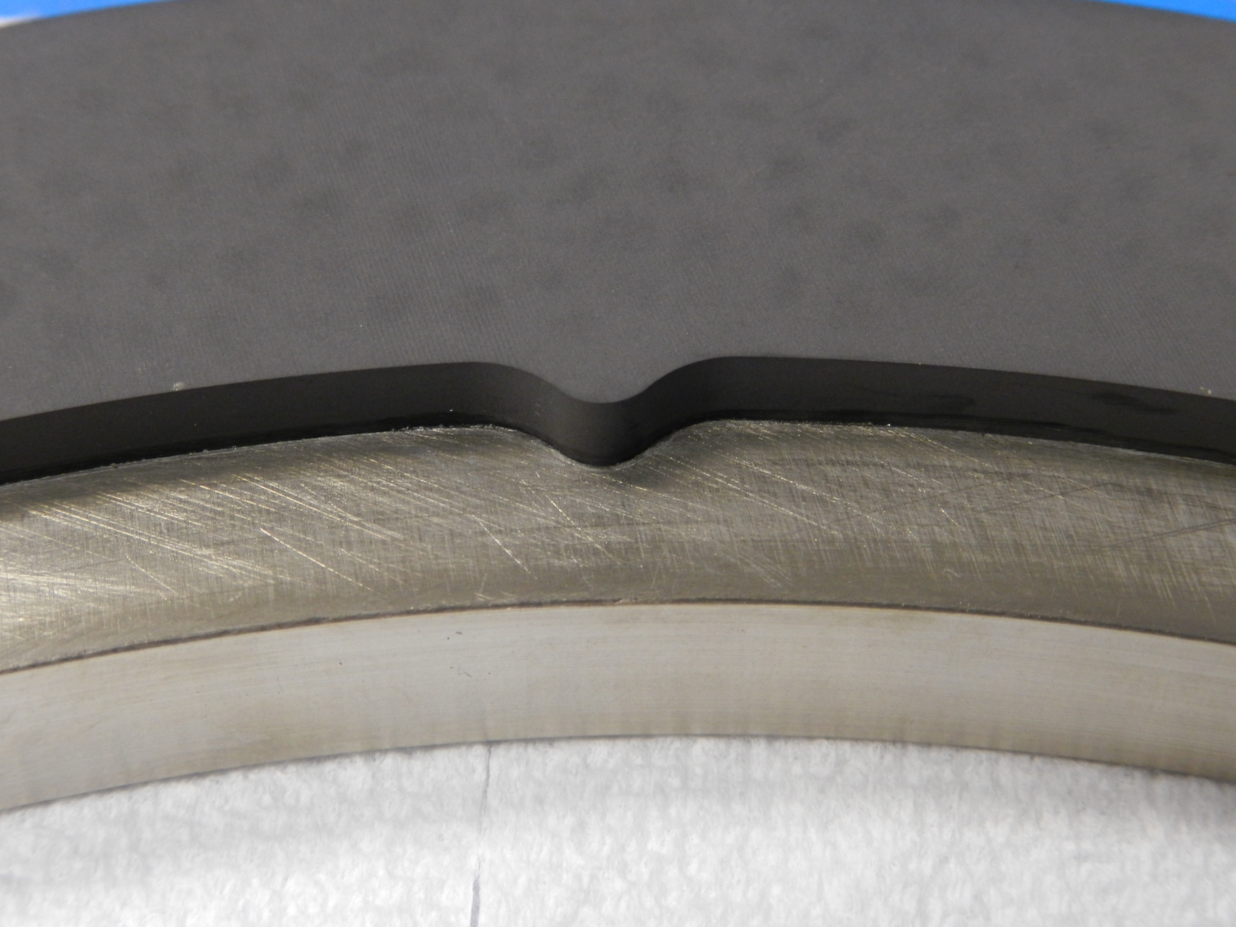
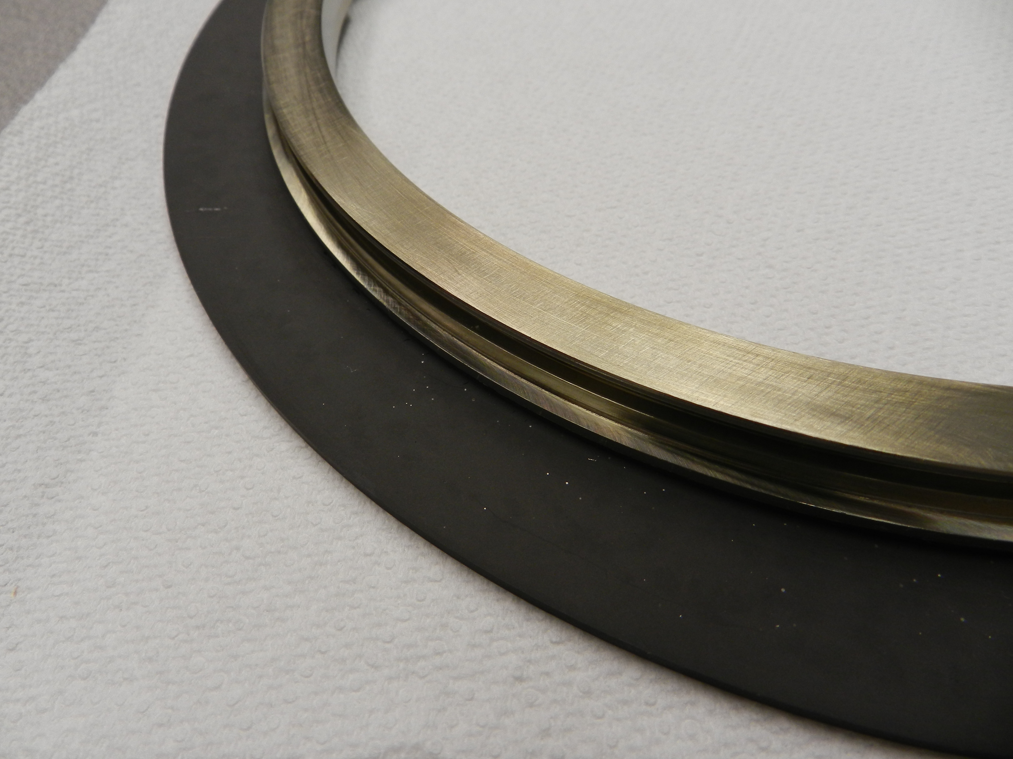
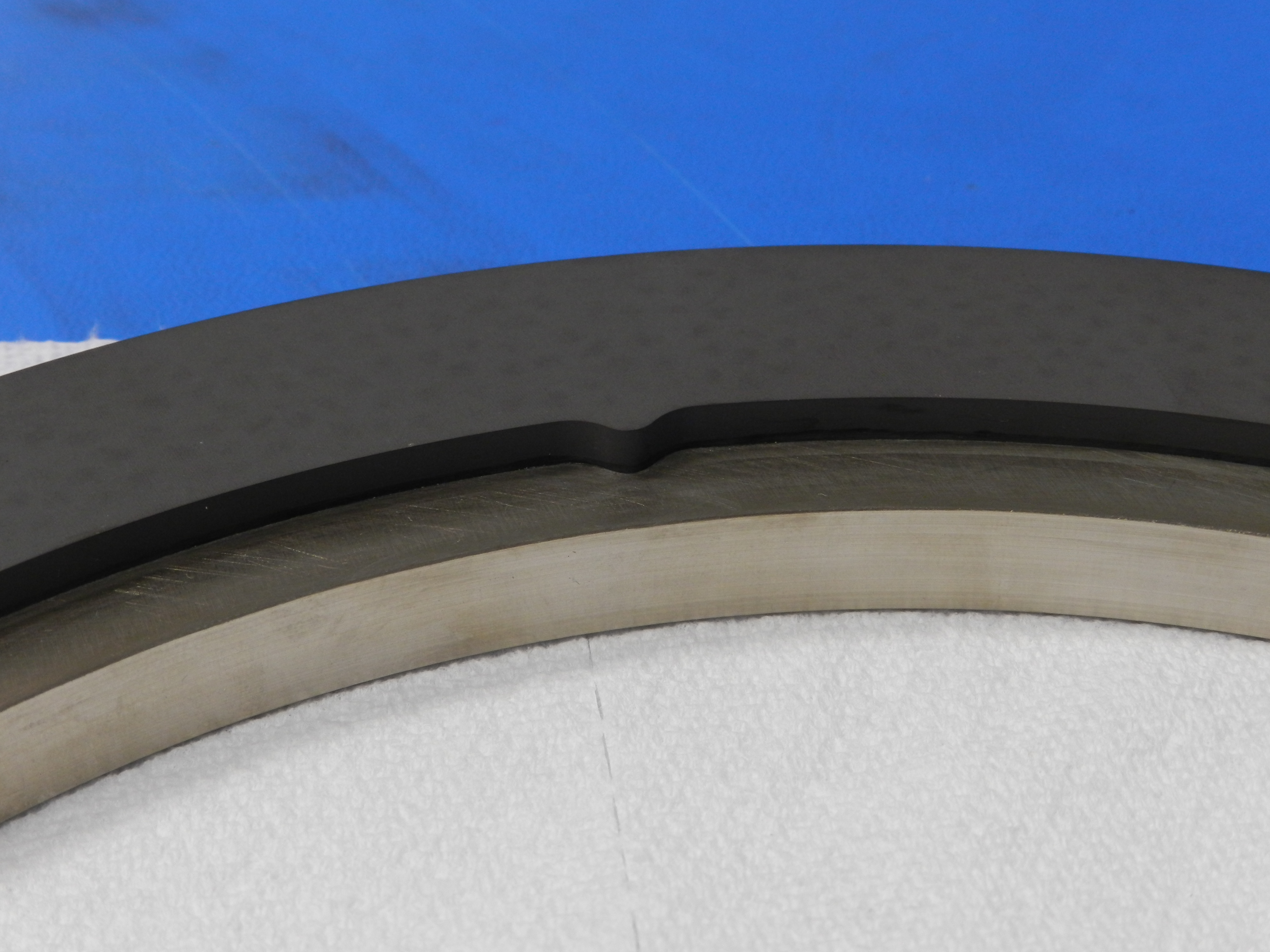
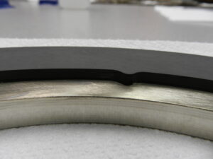 Carbon/graphite compressor seal rings are employed in many compressors and more and more metal backed graphite seals are being used in higher efficiency compressors. Frictional heating of seals can degrade metal backed graphite seals, therefore good thermal contact between the graphite seal ring and the metal backing is needed to improve cooling of the seal.
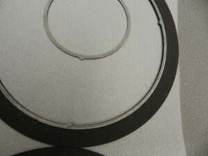
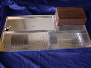 Copper has superior cooling capacity than aluminum and is the preferred heat sink material for telecommunications and high power electronics. However, the weight and cost or copper limits the size of the heat sink packages. Therefore for larger electronic enclosures a hybrid design, using copper for a localized heat sink joined to an aluminum frame with good thermal contact can significantly improve the cooling performance of a heat sink package.
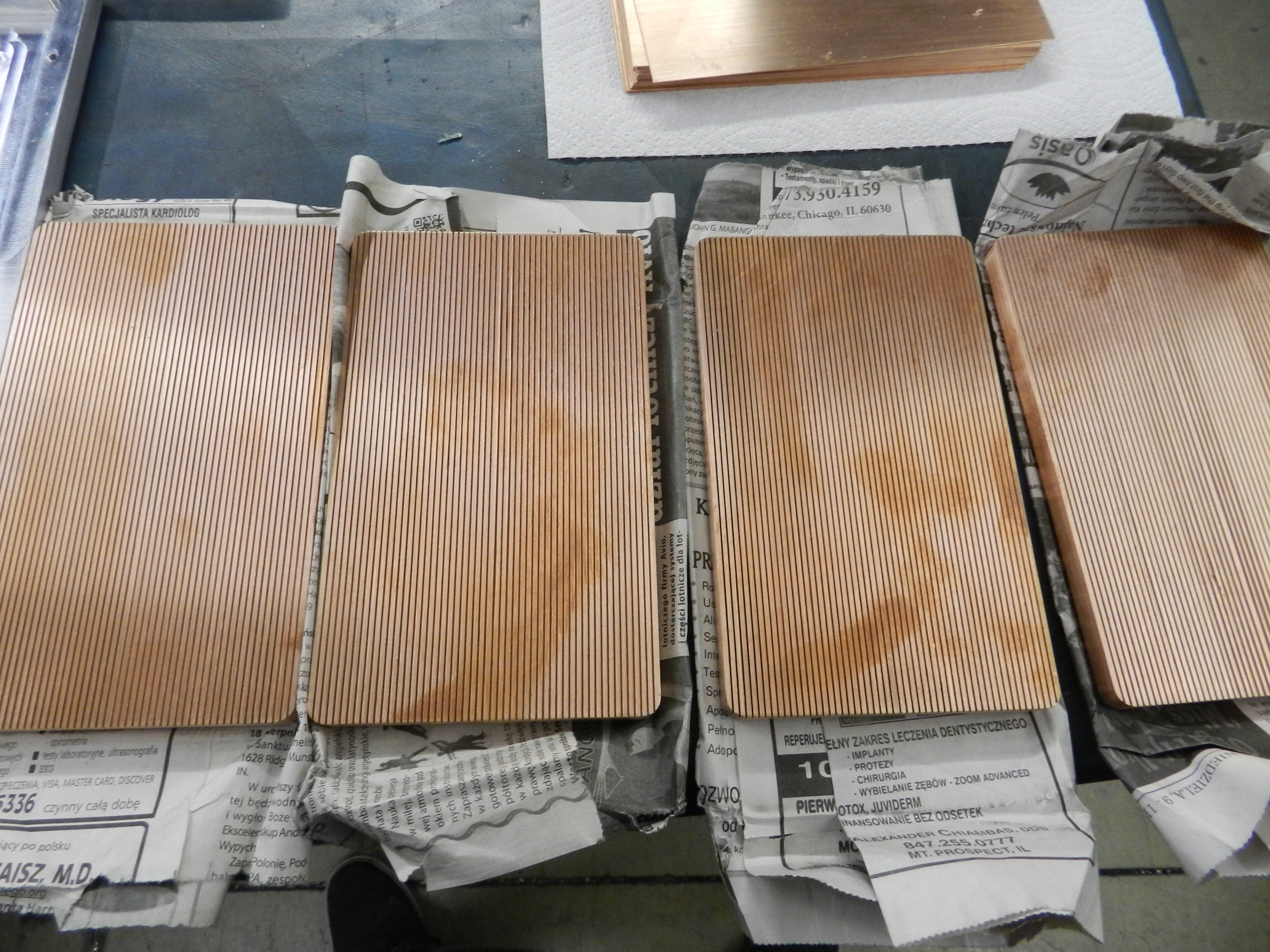


