Fabrication of Hybrid Cu-Al Finned Heat Sinks
 Copper has superior cooling capacity than aluminum and is the preferred heat sink material for telecommunications and high power electronics. However, the weight and cost or copper limits the size of the heat sink packages. Therefore for larger electronic enclosures a hybrid design, using copper for a localized heat sink joined to an aluminum frame with good thermal contact can significantly improve the cooling performance of a heat sink package.
Joining copper to aluminum poses it challenges. Cu and Al cannot be welded easily due to the intermetallics that form when Cu alloys with Al in the weld pool. Alternatively, brazing cannot be done since melt point of aluminum is below the typical Cu-Ag braze filler metals (silver solders) used to braze copper. These issues leave “soldering” as the metal filler joining process of choice. But alone, soldering of Cu to Al has challenges. Solders, typically Sn-Ag based, cannot easily wet and adhere to aluminum without first plating the aluminum with nickel or using very aggressive chemical fluxes which themselves are incompatible with soldering to copper.
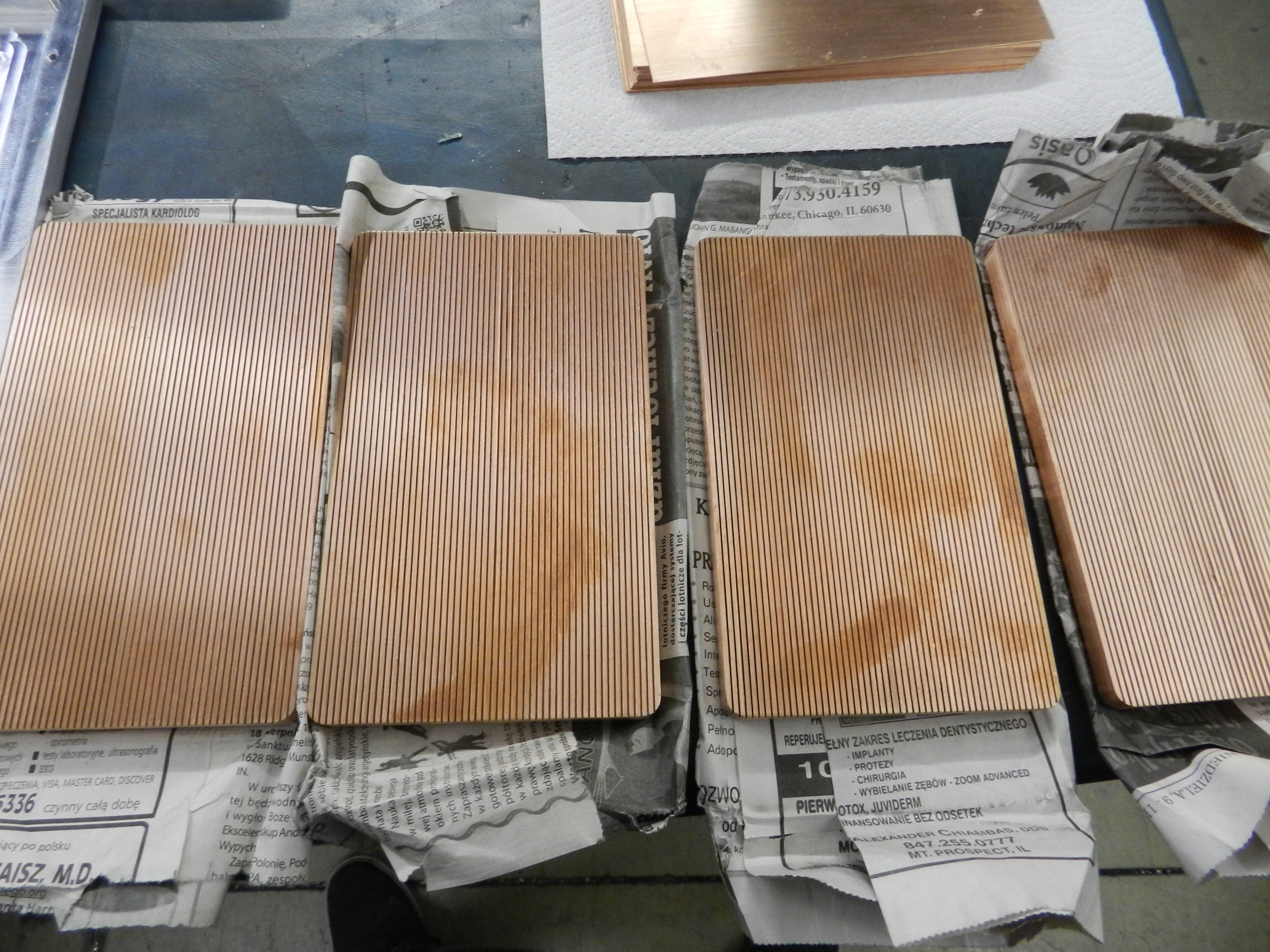
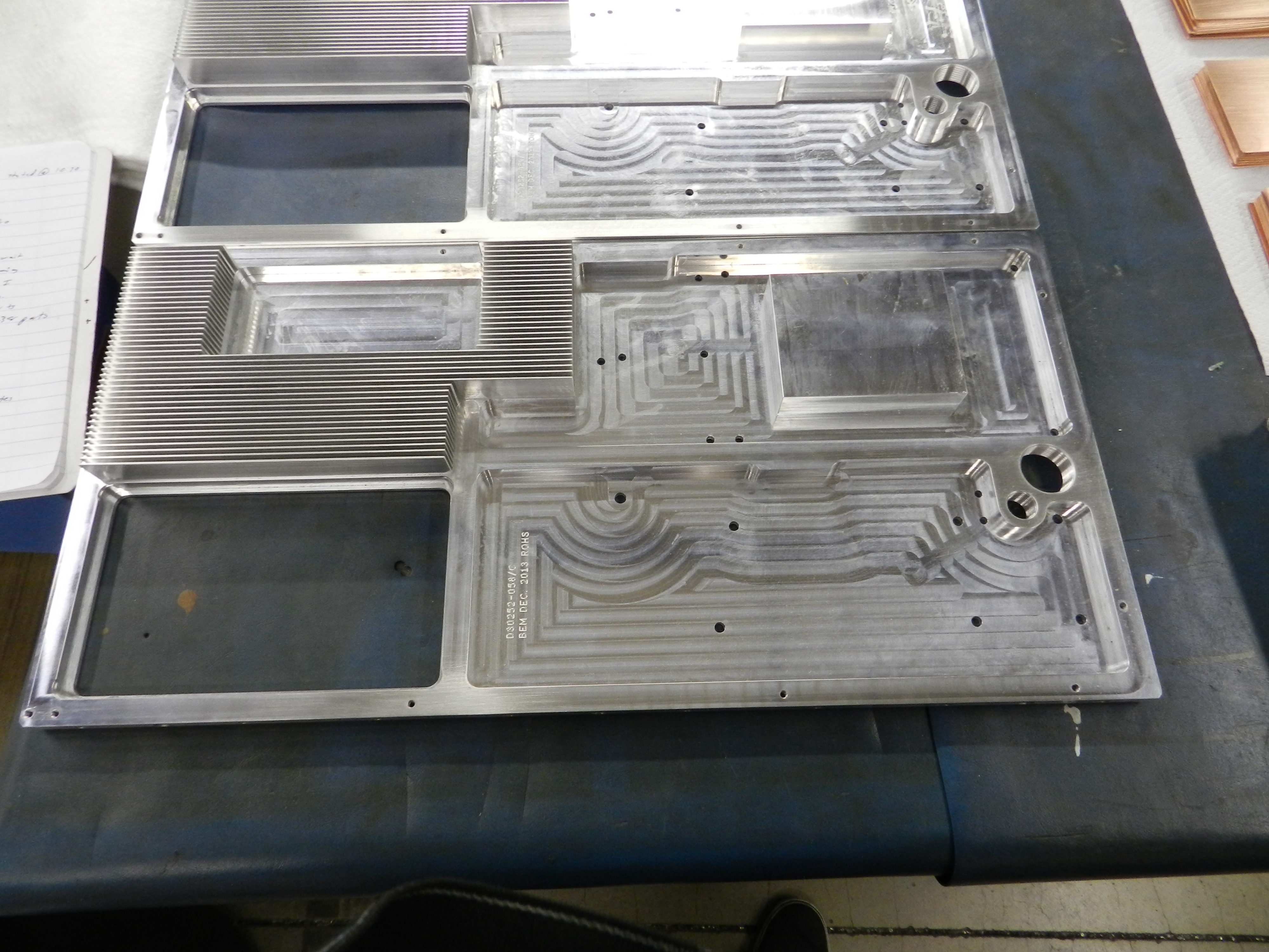
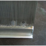
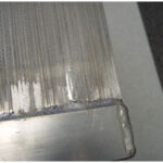
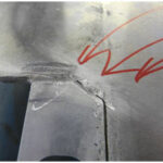
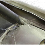
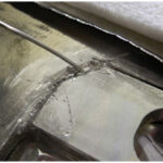
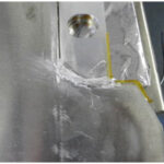
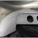
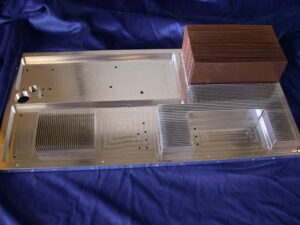
S-Bond Technologies, working with its customers has demonstrated its active solder, S-Bond 220-50, join Cu to Al in all configurations. The figures below show an example of where a copper- finned heat sink assembly was S-Bond joined into a finned aluminum package. In this assembly, the Cu-fins were individually S-Bond soldered into copper heat sink base, after which the Cu fin-base assembly was then S-Bond joined into the aluminum base at 250C. This soldering temperature well below the softening temperatures for the aluminum frame and low enough that the thermal expansion mismatch between Cu and Al did not distort the bonded assembly when cooling.
Hybrid heat sinks, combing the thermal benefits of copper with lightweight aluminum are taking advantage of the capabilities of active solder joining. For tough dissimilar materials and copper and aluminum bonding challenges, Contact us.